To improve the air flow into the 3.4L engine. Everyone says if the 3.4 could just breath better it could make more power. We will see when I get this intake on if it makes more power.
The engine vacum, at WOT, is above zero, so a better intake should help.
Ever since I saw Cooter's (Greg) dual tb intake on Penncocks Fiero Fourm I wanted it! He had it for sale, but someone else bought it. Shaun41178 They have it installed and running, but I have not heard any dyno numbers.
Take scrap metal I have laying around and form (read as grind and weld) it into a dual tb intake system like Greg made. Each intake will feed three cylinders, and each intake will have its own stock fiero TB. I happen to have two stock TB to use.
requirements:
reuse the stock middle intake
bolt square metal tubing to it with the stock mounting holes
bolt the stock TB to the driver side end of the square tubing
not modify the stock TB (I might need to use it later)
So far I have done the following:
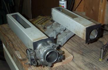
Cut rear side intake tube from 3"x3"x1/16" inch metal tube. I welded some 1/8" plate on one end to close it off.
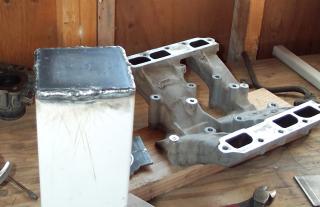
Cut the holes in tube to match middle intake holes
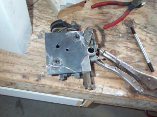
Fabricated one TB mounting plate out of 3/16" inch plate, notice the cut out to clear the coolant line hoses. Also note the nuts welded on the back side that will hold on the TB.
One of the many test fittings These are ready to be welded together.
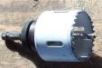
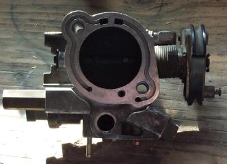
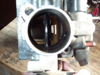
All welded and bolted together. The 2 1/8" hole is drilled for the tb. This is looking through the TB to the holes to the middle intake. There are no restrictions to impeed the air flow. This should flow a lot more air than the stock plenum with only one tb.
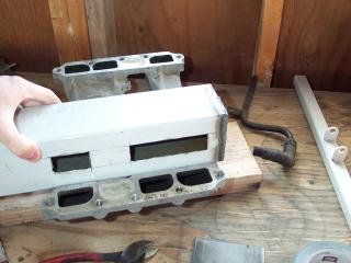
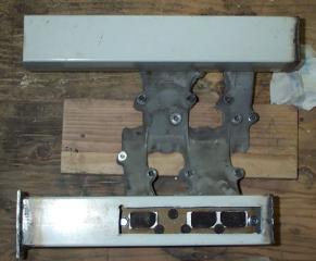
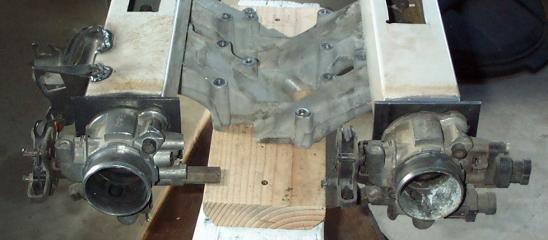
Holes cut and rear upper intake mounted to the middle intake. I decided to cut a hole in the top to access the bolts holding the upper intake to the middle intake. I will cover it will a plate and several screws when finished. Also notice I have started mounting the front intake. Yes it is longer than the rear upper intake, but the plates where the tbs go will line up and I will use a bar linkage so that they both turn together.
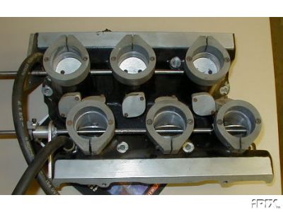
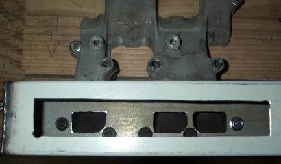
Holes to the middle intake, with the upper intake mounted to the middle intake. Holes on this side are better than the first side. If I do it agian they will be better still. They are not bad for a drill, jigsaw, and file.
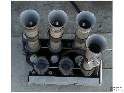
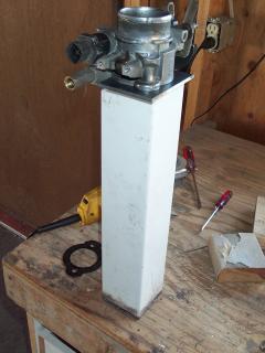
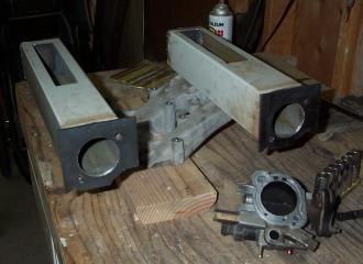
Here are both upper intakes mounted and one tb installed. I will have to take the other TB off the fiero to fit it, or source one from a local fiero owner.
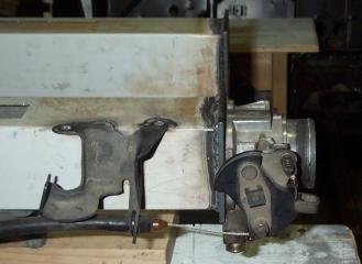
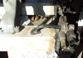
Here is the cable mount welded on and a throttle cable pulling on the TB. Works good I can't wait to get it on the car.
Here is the second TB on the intake. Next is to took them together.
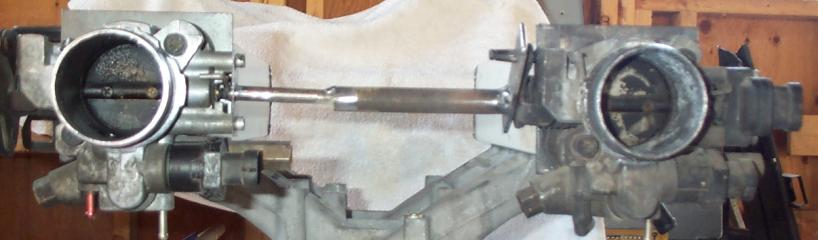
The linkage that makes the the TBS open together. The front side TB has the TPS removed, and in its place is a rod. The rod is rotated the same as the TPS is operated. The rod connects to the rear TB where the cables used to attach. The cable mech was easily removed by taking off the clip and pulling it off. A made a plate to attach where the cable mech was, I welded a metal tube off the plate. I slipped the rod inside the tube. The two pieces (the rod and tube/plate) were then tack welded together in the middle while mounted. Both TBs open together and they open fully. The TPS and IAC will be on the rear TB.
Here is the idle air took up. The IAC and TPS will only be hooked up on the rear tb, so air must be able to pass from side to side so all six cylinders will breath when idling. The AIC will let air from the infront of the rear TB into the black tube. The black tube is welded over a hole in the upper intake. That is part of the stock idle air tube. Obviously the picture is taken of the bottom of the intake.
I have welded the center bar in. The center bar is be 1"x1" square tube to transfer air between the pair of upper intakes and to help hold the intakes together when bolted down. Also notice the little nut welded to the right side of the left intake in the picture. That is the mount for the MAP sensor.
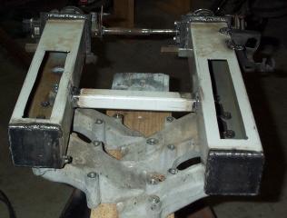
I also measured for the trunk lid clearence. The TBS will clear the trunk lid and the support rails in the trunk lid. The piping to the TBs will be tight.
I next have to run all the vacum lines. The vacum line for the brake booster will be attached to the front upper intake. The vacum lines for the MAP sensor and cruise will be tooked up to a hose from the front side intake.
I also have to cover the access holes on the top of the two new upper intakes. I will do that by welding nuts to the sides of the tubes and bolting down a 1/8" plate with silicone gasket material. If it leaks I will just weld the plate on and consider the intake permanatly attached to the middle intake.
I hope to not have to buy a haltech, dynotuner, or equivalent, to modify the fule/air mixture. I have an ALDL connector and can connect my laptop to the ecm, so I will use that to determine if it is rich or lean and adjust the fuel pressure accordingly. I might end up having to get a haltech. We will see.....
If you want to comment on my intake design or build, there is a thread on PFF that anyone can post in.